INTRODUCTION
Webster's New Collegiate Dictionary defines tool as:
tool, n. 1. Any instrument necessary to a person in the efficient prosecution of his trade or calling.
People in the construction industry use tools such as hammers, drills and saws to build structures. People in the movie industry use cameras, film and lights. To the engineer, tools exist in the form of physical tools like computers, calculators, etc. and analytical tools like procedures and analysis techniques. The Finite Element Method (FEM) is one particular analytical "tool" that allows engineers to calculate how physical systems will react when exposed to different conditions.
FEM has been in development for over 50 years. Initially it was applied to the structural analysis of complex objects such as aircraft wings and calculations were performed by hand. In recent years with improvements in FEM technology and its automation by computers, larger and more complex models can be analyzed. In addition to structural analysis, this method has been extended to other disciplines such as heat transfer, fluid flow and electromagnetics.
The size and complexity of the physical object to be analyzed determines how many calculations must be made. Some simple objects require only a few equations that can be solved by hand with a calculator. More complex objects require millions of calculations. The DYNA3D, ABAQUS or Altair HyperMesh computer programs, based on the finite element method, will be used to study how mechanical systems react under load to gain insight on how to improve the designs.
DYNA3D-dynamics in three dimensions, is a nonlinear structural dynamics code that can analyze the complex structural response of mechanical systems to high-rate loading and impacts. Basically, the program simulates the effect of stress on structures. DYNA is based on the finite element method and was developed over 20 years ago at the Lawrence Livermore National Lab to study the effects of weapons systems. The program is currently in use by over 14 Ohio faculty members on the Ohio Supercomputer machines. The 20 projects that are being investigated by the Ohio university faculty range from improving the crash worthiness of automobiles and highway safety structures to studying how different muscle forces affect the healing of tendons. LS-DYNA runs in parallel and can scale to up to 128 processors.
ABAQUS is a general purpose, production-oriented finite element program. It provides a variety of time and frequency-domain analysis procedures. These procedures include "general analysis," in which the response may be linear or nonlinear, "linear perturbation analyses," in which linear response is computed about a general, possibly nonlinear, base state and highly nonlinear transient dynamic phenomena.
HyperWorks is a high-perfomance, comprehensive toolbox of CAE software for engineering design and simulation. This package will provide the desktop environment in which the students will build their model. HyperWorks can be used to solve certain types of problems, or the models can be exported to one of the other solvers.
THE FINITE ELEMENT METHOD
The Finite Element Method (FEM) is an analysis technique that is applicable to a broad range of problems. With this technique systems are described by mathematical equations. While these equations can be derived for simple objects, finding a solution that describes a complete complex structure is generally not practical. FEM addresses this difficulty by dividing a complex system into smaller objects so that the solution for each object can be represented by an equation much simpler than that required by the entire system.
The smaller elements that make up the larger object are connected at discrete joints called nodes. For each element, approximate stiffness equations are derived relating the displacements of the nodes to the node forces between elements and a computer is used to solve the simultaneous equations that relate these node forces and displacements. Since the basic principle of subdivision of the structure into simple elements can be applied to structures of all forms and complexity, there is no logical limit to the type of structure that can be analyzed if the program is written in the appropriate form.
THE PROJECT
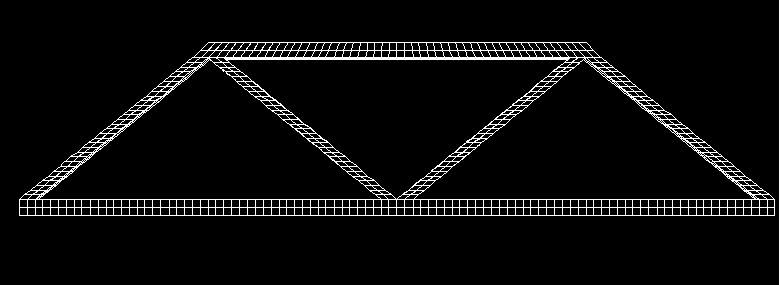
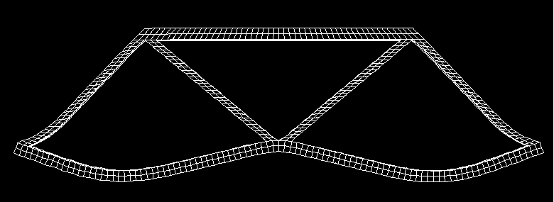
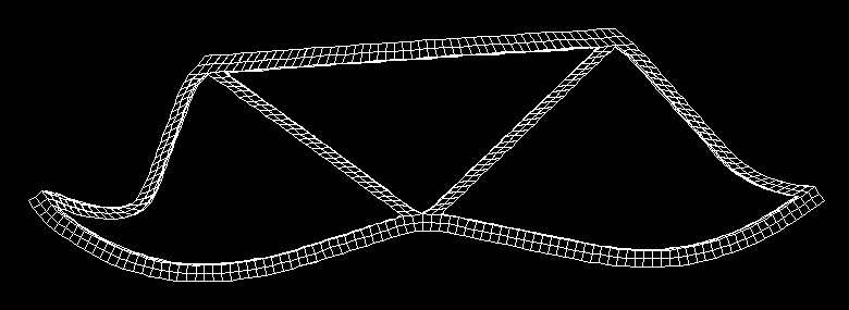
A common engineering problem presented to high school students is bridge design. Small-scale models that incorporate the basic design principles are often constructed to examine the strength of the design. For this project, students will study the mechanics of a basic bridge truss system. A model similar to that shown in Fig. 1 will be constructed for input to the DYNA3D program and different loads will be simulated. Results from the computer analysis will be visualized to show where the highest stresses build up in the system. Students will watch the model deform under higher loads until failure is achieved to show the correlation between the stresses visualized in the previous step and where failure actually occurs. Figures 2 and 3 are possible stages of the bridge truss system as it deforms.
Armed with this information, students will revise the design by moving or adding elements to the truss. The analysis and visualization steps will be repeated so that the impact of the changes can be seen. In addition to learning some basic design principals and gaining experience building models on the supercomputer, students will experience how computer predictions are used in the design process and how the information they calculate can be used to test and improve designs.

Figure 1

Figure 2

Figure 3
ANIMATIONS
SI2003
- Simulation of Project 1
- Simulation of Project 2
- Simulation of Project 3
- Simulation of Project 4
- Simulation of Project 5
- Simulation of Project 6
SI2002
- Simulation of Project (ATV disk brake analysis)
SI2001
- Simulation of Project (Cosmos 1 satellite design)
SI2000
- Simulation of Project (Car frame analysis)
SI1998
- Simulation of Project (Bridge collapse)
Jim Giuliani is the OSC coordinator for the Mechanical Engineering project. Jim's office is in 420-3. Please contact Jim to set up appointment(s) for consultation.
For assistance, write si-contact@osc.edu or call 614-292-0890.